Videos/Digital Show and Tell: Difference between revisions
→Bandlimitation and timing: moar terms, prose |
|||
| Line 391: | Line 391: | ||
:<math>\begin{align} | :<math>\begin{align} | ||
x_{\mathrm{square}}(t) | x_{\mathrm{square}}(t) = \frac{4}{\pi}\sin(\omega t) + \frac{4}{3\pi}\sin(3\omega t) + \frac{4}{5\pi}\sin(5\omega t) + \\ | ||
\frac{4}{7\pi}\sin(7\omega t) + \frac{4}{9\pi}\sin(9\omega t) + \frac{4}{11\pi}\sin(11\omega t) + \\ | |||
\frac{4}{13\pi}\sin(13\omega t) + \frac{4}{15\pi}\sin(15\omega t) + \frac{4}{17\pi}\sin(17\omega t) + \\ | |||
\frac{4}{19\pi}\sin(19\omega t) + \frac{4}{21\pi}\sin(21\omega t) + \frac{4}{23\pi}\sin(23\omega t) + \\ | |||
\frac{4}{25\pi}\sin(25\omega t) + \frac{4}{27\pi}\sin(27\omega t) + \frac{4}{29\pi}\sin(29\omega t) + \\ | |||
\frac{4}{31\pi}\sin(31\omega t) + \frac{4}{33\pi}\sin(33\omega t) + \cdots | |||
\end{align}</math> | \end{align}</math> | ||
| Line 397: | Line 402: | ||
We're using a quite sharp [[WikiPedia:Low-pass_filter|anti-aliasing filter]] that cuts off right | We're using a quite sharp [[WikiPedia:Low-pass_filter|anti-aliasing filter]] that cuts off right | ||
above 20kHz, so our signal is [[WikiPedia:Bandlimiting|bandlimited]], | above 20kHz, so our signal is [[WikiPedia:Bandlimiting|bandlimited]], so only the first ten terms make it through. | ||
..and that's exactly what we see on the output scope. | ..and that's exactly what we see on the output scope. | ||
The rippling you see around sharp edges in a bandlimited signal is | The rippling you see around sharp edges in a bandlimited signal is called the [[WikiPedia:/Gibbs_phenomenon|Gibbs effect]]. It happens whenever you slice off part of the frequency domain in the middle of nonzero energy. | ||
called the [[WikiPedia:/Gibbs_phenomenon|Gibbs effect]]. It happens whenever you slice off part of the | |||
frequency domain in the middle of nonzero energy. | |||
The usual rule of thumb you'll hear is "the sharper the cutoff, the | The usual rule of thumb you'll hear is "the sharper the cutoff, the | ||
Revision as of 08:54, 26 February 2013
Wiki edition
Continuing in the "firehose" tradition of Episode 01, Xiph.Org's second video on digital media explores multiple facets of digital audio signals and how they really behave in the real world.
Demonstrations of sampling, quantization, bit-depth, and dither explore digital audio behavior on real audio equipment using both modern digital analysis and vintage analog bench equipment, just in case we can't trust those newfangled digital gizmos. You can download the source code for each demo and try it all for yourself!
Supported players: VLC 1.1+, Firefox , Chrome , Opera. Or see other WebM or other Theora players.
If you're having trouble with playback in a modern browser or player, please visit our playback troubleshooting and discussion page.
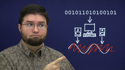
Hi, I'm Monty Montgomery from Red Hat and Xiph.Org.
A few months ago, I wrote an article on digital audio and why 24bit/192kHz music downloads don't make sense. In the article, I mentioned--almost in passing--that a digital waveform is not a stairstep, and you certainly don't get a stairstep when you convert from digital back to analog.
Of everything in the entire article, that was the number one thing people wrote about. In fact, more than half the mail I got was questions and comments about basic digital signal behavior. Since there's interest, let's take a little time to play with some simple digital signals.
Veritas ex machina
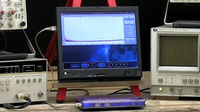
Pretend for a moment that we have no idea how digital signals really behave. In that case it doesn't make sense for us to use digital test equipment either. Fortunately for this exercise, there's still plenty of working analog lab equipment out there.
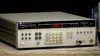
First up, we need a signal generator to provide us with analog input signals--in this case, an HP3325 from 1978. It's still a pretty good generator, so if you don't mind the size, the weight, the power consumption, and the noisy fan, you can find them on eBay... occasionally for only slightly more than you'll pay for shipping.
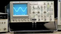
Next, we'll observe our analog waveforms on analog oscilloscopes, like this Tektronix 2246 from the mid-90s, one of the last and very best analog scopes ever made. Every home lab should have one.
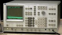
...and finally inspect the frequency spectrum of our signals using an analog spectrum analyzer, this HP3585 from the same product line as the signal generator. Like the other equipment here it has a rudimentary and hilariously large microcontroller, but the signal path from input to what you see on the screen is completely analog.
All of this equipment is vintage, but aside from its raw tonnage, the specs are still quite good.
At the moment, we have our signal generator set to output a nice 1 kHz sine wave at one Volt RMS. We see the sine wave on the oscilloscope, can verify that it is indeed 1 kHz at 1 Volt RMS, which is 2.8 Volts peak-to-peak, and that matches the measurement on the spectrum analyzer as well.
The analyzer also shows some low-level white noise and just a bit of harmonic distortion, with the highest peak about 70dB or so below the fundamental. Now, this doesn't matter at all in our demos, but I wanted to point it out now just in case you didn't notice it until later.
Now, we drop digital sampling in the middle.
For the conversion, we'll use a boring, consumer-grade, eMagic USB1 audio device. It's also more than ten years old at this point, and it's getting obsolete.
A recent converter can easily have an order of magnitude better specs. Flatness, linearity, jitter, noise behavior, everything... you may not have noticed. Just because we can measure an improvement doesn't mean we can hear it, and even these old consumer boxes were already at the edge of ideal transparency.
The eMagic connects to my ThinkPad, which displays a digital waveform and spectrum for comparison, then the ThinkPad sends the digital signal right back out to the eMagic for re-conversion to analog and observation on the output scopes.
Input to output, left to right.
Stairsteps
OK, it's go time. We begin by converting an analog signal to digital and then right back to analog again with no other steps.
The signal generator is set to produce a 1kHz sine wave just like before.
We can see our analog sine wave on our input-side oscilloscope.
We digitize our signal to 16 bit PCM at 44.1kHz, same as on a CD. The spectrum of the digitized signal matches what we saw earlier
and what we see now on the analog spectrum analyzer, aside from its high-impedance input being just a smidge noisier.
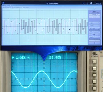
For now, the waveform display shows our digitized sine wave as a stairstep pattern, one step for each sample.
And when we look at the output signal that's been converted from digital back to analog, we see...
It's exactly like the original sine wave. No stairsteps.
OK, 1 kHz is still a fairly low frequency, maybe the stairsteps are just hard to see or they're being smoothed away. Fair enough. Let's choose a higher frequency, something close to Nyquist, say 15kHz.
Now the sine wave is represented by less than three samples per cycle, and...
the digital waveform looks pretty awful. Well, looks can be deceiving. The analog output...
is still a perfect sine wave, exactly like the original.
Let's keep going up.
Let's see if I can do this without blocking any cameras.
16kHz.... 17kHz... 18kHz... 19kHz...
20kHz. Welcome to the upper limits of human hearing. The output waveform is still perfect. No jagged edges, no dropoff, no stairsteps.
So where'd the stairsteps go? Don't answer, it's a trick question. They were never there.
Drawing a digital waveform as a stairstep... was wrong to begin with.
Why? A stairstep is a continuous-time function. It's jagged, and it's piecewise, but it has a defined value at every point in time.
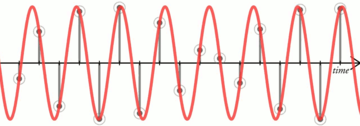
A sampled signal is entirely different. It's discrete-time; it's only got a value right at each instantaneous sample point and it's undefined, there is no value at all, everywhere between. A discrete-time signal is properly drawn as a lollipop graph.
The continuous, analog counterpart of a digital signal passes smoothly through each sample point, and that's just as true for high frequencies as it is for low.
Now, the interesting and not at all obvious bit is: there's only one bandlimited signal that passes exactly through each sample point. It's a unique solution. So if you sample a bandlimited signal and then convert it back, the original input is also the only possible output.
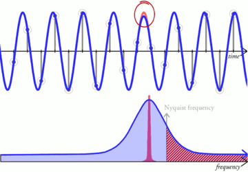
And before you say, "oh, I can draw a different signal that passes through those points", well, yes you can, but if it differs even minutely from the original, it includes frequency content at or beyond Nyquist, breaks the bandlimiting requirement and isn't a valid solution.
So how did everyone get confused and start thinking of digital signals as stairsteps? I can think of two good reasons.
First: it's easy enough to convert a sampled signal to a true stairstep. Just extend each sample value forward until the next sample period. This is called a zero-order hold, and it's an important part of how some digital-to-analog converters work, especially the simplest ones.
So, anyone who looks up digital-to-analog converter or digital-to-analog conversion is probably going to see a diagram of a stairstep waveform somewhere, but that's not a finished conversion, and it's not the signal that comes out.
Second, and this is probably the more likely reason, engineers who supposedly know better, like me, draw stairsteps even though they're technically wrong. It's a sort of like a one-dimensional version of fat bits in an image editor.
Pixels aren't squares either, they're samples of a 2-dimensional function space and so they're also, conceptually, infinitely small points. Practically, it's a real pain in the ass to see or manipulate infinitely small anything, so big squares it is. Digital stairstep drawings are exactly the same thing.
It's just a convenient drawing. The stairsteps aren't really there.
Bit-depth
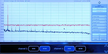
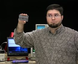
When we convert a digital signal back to analog, the result is also smooth regardless of the bit depth. 24 bits or 16 bits... or 8 bits... it doesn't matter.
So does that mean that the digital bit depth makes no difference at all? Of course not.
Channel 2 here is the same sine wave input, but we quantize with dither down to 8 bits.
On the scope, we still see a nice smooth sine wave on channel 2. Look very close, and you'll also see a bit more noise. That's a clue.
If we look at the spectrum of the signal... aha! Our sine wave is still there unaffected, but the noise level of the 8-bit signal on the second channel is much higher!
And that's the difference the number of bits makes. That's it!
When we digitize a signal, first we sample it. The sampling step is perfect; it loses nothing. But then we quantize it, and quantization adds noise.
The number of bits determines how much noise and so the level of the noise floor.
What does this dithered quantization noise sound like? Let's listen to our 8-bit sine wave.
That may have been hard to hear anything but the tone. Let's listen to just the noise after we notch out the sine wave and then bring the gain up a bit because the noise is quiet.
Those of you who have used analog recording equipment may have just thought to yourselves, "My goodness! That sounds like tape hiss!" Well, it doesn't just sound like tape hiss, it acts like it too, and if we use a gaussian dither then it's mathematically equivalent in every way. It is tape hiss.
Intuitively, that means that we can measure tape hiss and thus the noise floor of magnetic audio tape in bits instead of decibels, in order to put things in a digital perspective. Compact cassettes (for those of you who are old enough to remember them) could reach as deep as 9 bits in perfect conditions, though 5 to 6 bits was more typical, especially if it was a recording made on a tape deck. That's right... your mix tapes were only about 6 bits deep... if you were lucky!
The very best professional open reel tape used in studios could barely hit... any guesses? 13 bits with advanced noise reduction. And that's why seeing 'D D D' on a Compact Disc used to be such a big, high-end deal.
Dither
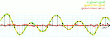
I keep saying that I'm quantizing with dither, so what is dither exactly and, more importantly, what does it do?
The simple way to quantize a signal is to choose the digital amplitude value closest to the original analog amplitude. Obvious, right? Unfortunately, the exact noise you get from this simple quantization scheme depends somewhat on the input signal,
so we may get noise that's inconsistent, or causes distortion, or is
undesirable in some other way.
Going deeper…
- Cameron Nicklaus Christou's thesis Optimal Dither and Noise Shaping in Image Processing provides an excellent explanation of dither and noise shaping.
Dither is specially-constructed noise that substitutes for the noise produced by simple quantization. Dither doesn't drown out or mask quantization noise, it actually replaces it with noise characteristics of our choosing that aren't influenced by the input.
Let's watch what dither does. The signal generator has too much noise for this test so we'll produce a mathematically perfect sine wave with the ThinkPad and quantize it to 8 bits with dithering.
We see a nice sine wave on the waveform display and output scope and, once the analog spectrum analyzer catches up... a clean frequency peak with a uniform noise floor on both spectral displays just like before. Again, this is with dither.
Now I turn dithering off.
The quantization noise, that dither had spread out into a nice, flat noise floor, piles up into harmonic distortion peaks. The noise floor is lower, but the level of distortion becomes nonzero, and the distortion peaks sit higher than the dithering noise did.
At 8 bits this effect is exaggerated. At 16 bits, even without dither, harmonic distortion is going to be so low as to be completely inaudible.
Still, we can use dither to eliminate it completely if we so choose.
Turning the dither off again for a moment, you'll notice that the absolute level of distortion from undithered quantization stays approximately constant regardless of the input amplitude. But when the signal level drops below a half a bit, everything quantizes to zero.
In a sense, everything quantizing to zero is just 100% distortion! Dither eliminates this distortion too. We reenable dither and ... there's our signal back at 1/4 bit, with our nice flat noise floor.
The noise floor doesn't have to be flat. Dither is noise of our choosing, so let's choose a noise as inoffensive and difficult to notice as possible.
Our hearing is most sensitive in the midrange from 2kHz to 4kHz, so that's where background noise is going to be the most obvious. We can shape dithering noise away from sensitive frequencies to where hearing is less sensitive, usually the highest frequencies.
16-bit dithering noise is normally much too quiet to hear at all, but let's listen to our noise shaping example, again with the gain brought way up...
Lastly, dithered quantization noise is higher Sound_power overall than undithered quantization noise even when it sounds quieter, and you can see that on a VU meter during passages of near-silence. But dither isn't only an on or off choice. We can reduce the dither's power to balance less noise against a bit of distortion to minimize the overall effect.
We'll also modulate the input signal like this to show how a varying input affects the quantization noise. At full dithering power, the noise is uniform, constant, and featureless just like we expect:
As we reduce the dither's power, the input increasingly affects the amplitude and the character of the quantization noise. Shaped dither behaves similarly, but noise shaping lends one more nice advantage. To make a long story short, it can use a somewhat lower dither power before the input has as much effect on the output.
Despite all the time I just spent on dither, we're talking about differences that start 100 decibels and more below full scale. Maybe if the CD had been 14 bits as originally designed, dither might be more important. Maybe. At 16 bits, really, it's mostly a wash. You can think of dither as an insurance policy that gives several extra decibels of dynamic range just in case. The simple fact is, though, no one ever ruined a great recording by not dithering the final master.
Bandlimitation and timing
We've been using sine waves. They're the obvious choice when what we want to see is a system's behavior at a given isolated frequency. Now let's look at something a bit more complex. What should we expect to happen when I change the input to a square wave...
The input scope confirms our 1kHz square wave. The output scope shows..
Exactly what it should.
...
What is a square wave really?
Well, we can say it's a waveform that's some positive value for half a cycle and then transitions instantaneously to a negative value for the other half.
But that doesn't really tell us anything useful about how that input becomes this output.
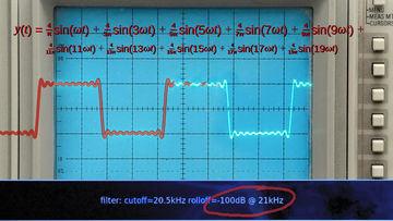
Then we remember that any waveform is also the sum of discrete frequencies, and a square wave is particularly simple sum: a fundamental and an infinite series of odd harmonics. Sum them all up, you get a square wave.
At first glance, that doesn't seem very useful either. You have to sum up an infinite number of harmonics to get the answer. Ah, but we don't have an infinite number of harmonics.
We're using a quite sharp anti-aliasing filter that cuts off right above 20kHz, so our signal is bandlimited, so only the first ten terms make it through.
..and that's exactly what we see on the output scope.
The rippling you see around sharp edges in a bandlimited signal is called the Gibbs effect. It happens whenever you slice off part of the frequency domain in the middle of nonzero energy.
The usual rule of thumb you'll hear is "the sharper the cutoff, the stronger the rippling", which is approximately true, but we have to be careful how we think about it. For example... what would you expect our quite sharp anti-aliasing filter to do if I run our signal through it a second time?
Aside from adding a few fractional cycles of delay, the answer is... nothing at all. The signal is already bandlimited. Bandlimiting it again doesn't do anything. A second pass can't remove frequencies that we already removed.
And that's important. People tend to think of the ripples as a kind of artifact that's added by anti-aliasing and anti-imaging filters, implying that the ripples get worse each time the signal passes through. We can see that in this case that didn't happen. So was it really the filter that added the ripples the first time through? No, not really. It's a subtle distinction, but Gibbs effect ripples aren't added by filters, they're just part of what a bandlimited signal is.
Even if we synthetically construct what looks like a perfect digital square wave,
it's still limited to the channel bandwidth. Remember, the stairstep representation is misleading.
What we really have here are instantaneous sample points,
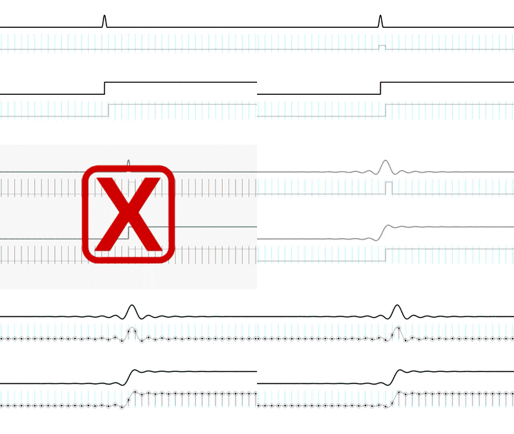
and only one bandlimited signal fits those points. All we did when we drew our apparently perfect square wave was line up the sample points just right so it appeared that there were no ripples if we played connect-the-dots.
But the original bandlimited signal, complete with ripples, was still there.
And that leads us to one more important point. You've probably heard that the timing precision of a digital signal is limited by its sample rate; put another way,
that digital signals can't represent anything that falls between the samples.. implying that impulses or fast attacks have to align exactly with a sample, or the timing gets mangled... or they just disappear.
At this point, we can easily see why that's wrong.
Again, our input signals are bandlimited. And digital signals are samples, not stairsteps, not 'connect-the-dots'. We most certainly can, for example, put the rising edge of our bandlimited square wave anywhere we want between samples.
It's represented perfectly and it's reconstructed perfectly.
Epilogue

Just like in the previous episode, we've covered a broad range of topics, and yet barely scratched the surface of each one. If anything, my sins of omission are greater this time around... but this is a good stopping point.
Or maybe, a good starting point. Dig deeper. Experiment. I chose my demos very carefully to be simple and give clear results. You can reproduce every one of them on your own if you like. But let's face it, sometimes we learn the most about a spiffy toy by breaking it open and studying all the pieces that fall out. And that's OK, we're engineers. Play with the demo parameters, hack up the code, set up alternate experiments. The source code for everything, including the little pushbutton demo application, is up at xiph.org.
In the course of experimentation, you're likely to run into something that you didn't expect and can't explain. Don't worry! My earlier snark aside, Wikipedia is fantastic for exactly this kind of casual research. And, if you're really serious about understanding signals, several universities have advanced materials online, such as the 6.003 and RES.6-007 Signals and Systems modules at MIT OpenCourseWare. And of course, there's always the community here at Xiph.Org.
Digging deeper or not, I am out of coffee, so, until next time, happy hacking!
Credits
Written by: Christopher (Monty) Montgomery and the Xiph.Org Community
Special thanks to:
- Heidi Baumgartner, for the second Tektronix oscilloscope
- Gregory Maxwell and Dr. Timothy Terriberry, for additional technical review
Intro, title and credits music:
"Andy Warhol Is Gone", by Lousy Robot
Used by permission of Lousy Robot.
Original source track All Rights Reserved.
www.lousyrobot.com
This Video Was Produced Entirely With Free and Open Source Software:
All trademarks are the property of their respective owners.
A Co-Production of Xiph.Org and Red Hat, Inc.
(C) 2012-2013, Some Rights Reserved
Use The Source Luke
As stated in the Epilogue, everything that appears in the video demos is driven by open source software, which means the source is both available for inspection and freely usable by the community. The Thinkpad that appears in the video was running Fedora 17 and Gnome Shell (Gnome 3). The demonstration software does not require Fedora specifically, but it does require Gnu/Linux to run in its current form. In all, the video involved about 50,000 lines of new and custom-purpose code (including contributions to non-Xiph projects such as Cinelerra and Gromit).
The Spectrum and Waveform Viewer
The realtime software spectrum analyzer application that appears in the video was a preexisting application that was dusted off and updated for use in the video. The waveform viewer (effectively a simple software oscilloscope) was written from scratch making use of some of the internals from the spectrum analyzer application. Both are available from Xiph.Org svn:
- Source for the Spectrum and Waveform applications is found at:
https://svn.xiph.org/trunk/spectrum/
- The source can be checked out of svn using the following command line:
svn co https://svn.xiph.org/trunk/spectrum
- Trac is a convenient way to browse the source without checking out a copy:
Spectrum and Waveform both expect an input stream on the command line, either as raw data or as a WAV file.
GTK-Bounce
The touch-controlled application used in the video is named 'gtk-bounce' and was custom-written for the sole purpose of the in-video demonstrations. It is so named because, for the most part, all it does is read the input from an audio device, and then immediately write the same data back out for playback. It also forwards a copy of this data to up to two external monitoring applications, and in several demos, applies simple filters or generates simple waveforms. It includes several demos not included in the video.
- Source for gtk-bounce is found at:
https://svn.xiph.org/trunk/Xiph-episode-II/bounce/
- The source can be checked out of svn using the following command line:
svn co https://svn.xiph.org/trunk/Xiph-episode-II/bounce/
- Trac is a convenient way to browse the source without checking out a copy:
The application is somewhat hardwired for specific demo purposes, but most of the hardwired settings can be found at the top of each source file. As found in SVN, the application expects an ALSA hardware audio device at hw:1, and if none if found, it will wait for one to appear. Once a sound device is successfully initialized, it expects to find and open two pipes named pipe0 and pipe1 for output in the current directory. In the video, the waveform and spectrum applications are started to take input from pipe0 and pipe1 respectively. The output sent to the two pipes is identical, and in most demos matches the output data sent to the hardware device for conversion to analog. The only exception is the tenth demo panel (which does not appear in the video) where gtk-bounce can be set to monitor the hardware inputs instead while the outputs are used to produce test waveforms.
Assuming gtk-bounce, spectrum and waveform have been checked out and built, the configuration seen in the video can be started using the following commands:
- make the pipe fifos for the applications to communicate (only needs to be done once)
mkfifo pipe0 pipe1
- start all three applications
waveform pipe0 & spectrum pipe1 & gtk-bounce &
Gtk-bounce consists of ten pushbutton panels that can be selected by scrolling up and dwon with the arrow buttons on the right side. Each panel is intended for a specific demo or part of a demo.
- Panel 1: This panel presents buttons that allow the sound card to be configured in several sampling rates and bit depths. Sampled read from the audio inputs are sent to the output pipes and audio outputs for playback without modification.
- Panel 2:
- Panel 3:
- Panel 4:
- Panel 5:
- Panel 6:
- Panel 7:
- Panel 8:
- Panel 9:
- Panel 10:
Cairo Animations
The animations featured throughout the Episode 2 video were rapid-development spaghetti hack-jobs coded by hand in raw Cairo. Each module generated a series of PNG stills that were then stitched into an animation with Cinelerra or mplayer. In the interest of pointing and laughing at what really bad code looks like...
- Source for the Cairo animations is found at:
https://svn.xiph.org/trunk/Xiph-episode-II/cairo/
- The source can be checked out of svn using the following command line:
svn co https://svn.xiph.org/trunk/Xiph-episode-II/cairo/
- Trac is a convenient way to browse the source without checking out a copy:

